


Catalytic combustion equipment
Keywords:
Catalytic combustion equipment
Category:
Product Description
Process characteristics and flow of catalytic combustion equipment
Process characteristics
1. Simple operation and stable running;
2. Maximize equipment safety;
3. Reasonable layout, low investment, and low operating costs;
4. The most reliable treatment process and the lowest maintenance costs;
5. Pursuing the highest purification efficiency.
Process selection description
Organic waste gas treatment refers to the use of various technical measures to reduce the amount of organic solvents used or purify exhaust gas to eliminate organic waste gas pollution. Organic waste gas pollution sources are widely distributed. To prevent pollution, in addition to reducing the amount of organic solvents used to reduce the generation and emission of organic waste gas, exhaust gas purification is a currently feasible treatment method; common methods include adsorption, absorption, combustion, condensation, and biological methods. When selecting a purification method, the method with low cost, low energy consumption, and no secondary pollution should be prioritized according to the specific situation, and efforts should be made to turn harm into benefit and fully recover components and waste heat;
According to the owner's requirements and our company's long-term experience in treating organic waste gas, the "dry filtration + adsorption desorption + catalytic combustion device" process is adopted. The working mode is two adsorption beds, one for adsorption and one for desorption. The actual working air volume of each adsorption bed is 10,000 m³/h, and the activated carbon is honeycomb-shaped. The adsorption and desorption cycle switches and operates continuously (the working time is adjusted according to the specific production situation).
Because the waste gas source contains a small amount of particulate matter, dry filtration is added before the waste gas enters the adsorption tank. Small particulate matter is removed after the first filtration, so no particulate matter enters the activated carbon tank. Considering that the flue gas temperature around the curing furnace is too high, it is necessary to add spray cooling before dry filtration.
The inlet and outlet valves of activated carbon and the inlet and outlet of desorption regeneration gas use pneumatic/electric valves for automatic control, and the electric actuators use imported products.
Desorption regeneration uses a catalytic combustion device. Flame arresters are installed at its inlet and outlet, and a bypass electric valve is installed. When the concentration is too high, the valve automatically opens and alarms, and fresh air is supplemented to reduce the temperature entering the adsorption bed.
Temperature measuring points are set in the adsorption bed, desorption pipeline, and catalytic purification device. The temperature changes of adsorption and desorption can be safely understood during the entire process, and the signals are transmitted to the PLC for safety control.
The entire system uses PLC control. The PLC uses the Siemens brand, and the 10-inch Taiwan Weinview touch screen displays the system operating status. The main electrical components use imported Schneider products. The entire system ensures the safe operation of the direct discharge system, adsorption system, desorption system, and fan overload short-circuit protection.
The fan uses products from domestic fan factories, connected with flexible hoses at the inlet and outlet, and equipped with vibration damping devices.
The adsorption bed is made of carbon steel plates and has an activated carbon inspection door. The catalyst in the catalytic device uses honeycomb ceramic catalyst, and key parts are made of stainless steel.
Process flow chart
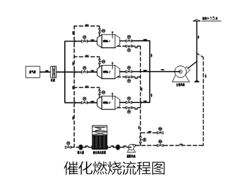
Process flow description
The organic waste gas treatment project process flow mainly includes four parts: waste gas collection---filtration---adsorption gas flow---desorption gas flow---control system
1. Spraying and filtration device:
Waste gas treatment process: Waste gas enters---dry filtration section (removal of fine dust particles)---outlet to activated carbon adsorption device;
Equipment composition: Composed of inlet section, dry filter, inspection door, and outlet section.
2. Adsorption gas flow:
The organic waste gas to be treated is introduced from the duct into the activated carbon adsorption bed. After the gas enters the adsorption bed, the organic substances in the gas are adsorbed by the activated carbon and adhere to the surface of the activated carbon, thereby purifying the gas. The purified gas is then discharged into the atmosphere by the fan (the final discharged gas concentration meets the environmental protection standards, and the purification efficiency is about 60-90%);
3. Control system:
The control system controls the fan, preheater, temperature, and electric valves in the system. When the system temperature reaches the predetermined catalytic temperature, the system automatically stops heating the preheater. When the temperature is insufficient, the system restarts the preheater to maintain the catalytic temperature within an appropriate range; when the temperature of the catalytic bed is too high, the cold air valve is opened to supplement fresh air into the catalytic bed system, which can effectively control the temperature of the catalytic bed and prevent the temperature of the catalytic bed from being too high;
PLC program control, touch screen display, and automatic switching of inlet and outlet and valves used in turn are used. Adsorption time and desorption time parameters can be set and adjusted. Ensure continuous, reliable, and stable compliance.
Introduction to catalytic combustion purification equipment
Dry filtration
Filtration---primary filtration layer-medium efficiency filtration layer;
According to the customer's production process, in order to ensure that the waste gas source (gas containing dust and paint mist) enters the adsorption purification device system to ensure that the gas source of the adsorption treatment system is clean, dry, and particle-free; the waste gas first enters the dry filtration section, and the gas containing organic solvents after preliminary purification enters the activated carbon adsorption device.
► The filter housing is made of Q235 t=3mm steel plate, with continuous welding on the outside, no bubbles, slag, etc., and the overall appearance is beautiful;
► The filter material uses a pleated filter layer, which has the characteristics of large air volume, low resistance, and large dust holding capacity;
► A differential pressure gauge (pointer type) is installed on the filtration section. When the internal differential pressure of the equipment exceeds 300Pa, it prompts to clean or replace the filter cotton;
Activated carbon adsorption device
♦ The adsorption tank is made of carbon steel, painted on the outside, and filled with a certain amount of activated carbon. A high-temperature detection device is installed. When waste gas containing organic matter is passed through the activated carbon adsorption layer (neatly stacked) by the action of the fan, the organic matter is retained inside by the unique force of the activated carbon, and the clean gas is discharged; after a period of time, when the activated carbon reaches saturation, adsorption is stopped, at which time the organic matter has been concentrated in the activated carbon; (the saturation time needs to be calculated based on the originally measured concentration, or set by experience);
♦ The outer shell of the adsorption tank is made of Q235 t=3mm steel plate, with continuous external welding, no bubbles, slag, etc., and the overall appearance is beautiful;
♦ Internal circulation pipeline: The internal circulation pipeline is made of t=1.5mm galvanized steel plate, with folded edge and snap-on connection, beautiful overall appearance, good sealing performance, and flange connection using bolts;
♦ Waste gas collection pipeline is made of galvanized aluminum plate, with folded edge and snap-on connection, beautiful overall appearance, good sealing performance, and flange connection using bolts; (if needed)
♦ The main exhaust fan uses high-quality domestic products, with the following specific requirements:
• The fan uses a 4-72 centrifugal fan, two units, no temperature resistance requirement, belt wheel drive;
• The housing material is made of high-quality steel, and the impeller material is 16Mn;
• The balance grade of the fan is above 5.6; the noise is no more than 85dB (A); it has no impact on the outside of the factory.
• The parameters of the fan air volume and pressure meet the design requirements, and the performance is stable;
♦ Chimney: The chimney is made of t=4mm carbon steel plate; the chimney height is +15 meters;
♦ Activated carbon uses coal-based, honeycomb-shaped activated carbon, with a bulk density of 400-450kg/m³;
Catalytic purification device
The catalytic purification device is equipped with a natural gas heating chamber. When the heating device is started and enters the internal circulation, when the hot gas source reaches the boiling point of the organic matter, the organic matter runs out of the activated carbon and enters the catalytic chamber for catalytic decomposition into CO2 and H2O, while releasing energy. The released energy is then used to desorb in the adsorption bed, at which time the heating device completely stops working, the organic waste gas maintains self-combustion in the catalytic combustion chamber, the exhaust gas is regenerated, and the cycle continues until the organic matter is completely separated from the activated carbon and decomposed in the catalytic chamber, the activated carbon is regenerated, and the organic matter is catalytically decomposed; for intermittent desorption, the heating device needs to be started each time, and continuous desorption does not require heating power.
Catalytic combustion: Using a catalyst as an intermediate, organic gases are converted into harmless water and carbon dioxide gas at a lower temperature, i.e.:
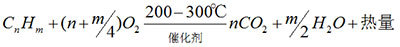
The organic gas desorbed from the saturated activated carbon is sent to the purification device by the action of the desorption induced draft fan (the organic solvent desorbed from the activated carbon is in gaseous form). First, it passes through the dust removal and flame arrester system, then enters the heat exchanger, and then is sent to the heating chamber. Through the heating device, the gas reaches the combustion reaction temperature, and then through the action of the catalytic bed, the organic gas is decomposed into carbon dioxide and water, and then enters the heat exchanger to exchange heat with the low-temperature gas, so that the temperature of the incoming gas is increased to reach the reaction temperature. If the reaction temperature is not reached, the heating system can compensate for heating through the automatic control system to ensure complete combustion, thus saving energy, and the effective removal rate of waste gas meets the emission standards and complies with national emission standards; the catalytic purification efficiency is over 97%.
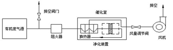
This device consists of a main unit, an induced draft fan, and an electrical control cabinet. The main unit of the purification device consists of a heat exchanger, a catalytic bed, an electric heating element, a flame arrester and dust remover, and an explosion-proof device, etc. The flame arrester and dust remover are located on the intake pipe, and the explosion-proof device is located at the top of the main unit. The process flow diagram is as follows:
Equipment features
♦ Precious metals palladium and platinum are plated on a honeycomb ceramic carrier as a catalyst, with high purification efficiency, long catalyst service life, smooth gas flow, and low resistance.
♦ Complete safety facilities: Equipped with flame arrester and dust remover, pressure relief port, over-temperature alarm, nitrogen protection, and other protective facilities.
♦ Power consumption: When starting work, preheat for 15-30 minutes at full power, and only consume fan power during normal operation. When the waste gas concentration is low, automatic intermittent compensation heating is used.
Advantages of the device
♦ This equipment has advanced design principles, unique materials, stable performance, simple operation, safety and reliability, and no secondary pollution. The equipment has a small footprint and light weight. The adsorption bed adopts a drawer-type structure, which is convenient for loading and easy to replace.
♦ A new type of activated carbon adsorption material—honeycomb activated carbon—is used. Compared with granular (rod-shaped) activated carbon, it has superior thermodynamic properties, low resistance and low consumption, and high adsorption rate, making it ideal for use under large air volumes.
♦ The catalytic combustion chamber uses a precious metal catalyst with a ceramic honeycomb structure, which has low resistance and can operate normally with a low-pressure fan, not only consuming less electricity but also having low noise.
♦ The air volume of the catalytic combustion device is one-tenth of the waste gas source air volume (referring to the desorption heating air volume of the catalytic purification device)
♦ The activated carbon bed that adsorbs organic waste gas can be desorbed and regenerated using the heat generated by the catalytic combustion treatment of waste gas. The desorbed gas is then sent to the catalytic combustion chamber for purification, without the need for external energy, resulting in low operating costs and good energy-saving effects.
Material requirements for the entire device
♦ The external frame of the equipment is made of Q235 t=1.2mm galvanized aluminum plate, with paint on the outside, and a beautiful overall appearance;
♦ The equipment panel is made of Q235 t=1.2mm galvanized aluminum plate, with paint on the outside, and a beautiful overall appearance;
♦ The equipment insulation uses 100kg/m³ rock wool insulation, with an insulation thickness of 100mm, and excellent insulation effect;
♦ The catalytic combustion chamber is made of Q235 t=4mm carbon steel plate, with good overall temperature resistance;
♦ The heat exchanger is made of Q235 t=1.2mm carbon steel plate, with continuous external welding and good internal sealing performance, and high heat exchange efficiency;
♦ The equipment connecting pipes are made of Q235 t=1.2mm thick galvanized aluminum zinc plate, with continuous external welding and overall aesthetics;
♦ The main exhaust fan uses high-quality domestic products, with the following specific requirements:
• The fan uses a 4-72 centrifugal fan, which can be used continuously below 250℃, and is belt-driven;
• The housing material is made of high-quality steel, the impeller material is 16Mn, and the bearings are NSK bearings;
• The fan's balance grade is above 5.6; the noise is no more than 85dB(A);
• The fan air volume, air pressure, and other parameters meet the design requirements and are stable in performance;
♦ The catalyst of the equipment has an outer dimension of 100×100×50mm, with high space velocity and good temperature resistance, and can work continuously at 200-300℃;
♦ The electric heating tube of the equipment uses carbon steel bright tube heating, which is easy to clean and has good heating effect;
Technical Performance and Characteristics of the Complete Set of Equipment
A. This equipment has advanced design principles, unique materials, stable performance, simple operation, safety and reliability, and no secondary pollution. The equipment has a small footprint and light weight.
B. A new type of activated carbon adsorption material—honeycomb activated carbon—is used. Compared with granular (rod-shaped) activated carbon, it has superior thermodynamic properties, low resistance and low consumption, and high adsorption rate, making it ideal for use under large air volumes.
C. The catalytic combustion chamber uses a noble metal catalyst with a ceramic honeycomb structure, which has low resistance and can operate normally with a low-pressure fan, resulting in low power consumption and low noise.
D. The activated carbon bed that adsorbs organic waste gas can be desorbed and regenerated using the heat generated by the catalytic combustion treatment of the waste gas. The desorbed gas is then sent to the catalytic combustion chamber for purification, requiring no additional energy, resulting in low operating costs and significant energy savings.
Description of Main Components of the Complete Set of Equipment
Activated Carbon Adsorption System
► Activated carbon adsorption: The core part of the entire device, using its own adsorption performance to purify organic waste gas;
► Adsorption fan: Uses a rear-induced draft type, allowing the device to operate under negative pressure;
► Overtemperature alarm system: Ensures the safe operation of the entire system during the desorption process;
► Thermocouple: Uses a stainless steel protective tube to measure the carbon layer temperature during desorption;
► Airflow regulating valve: Uses an electric valve, with a high-quality brand electric actuator;
► Control system: The entire system uses PLC control, which is safe and reliable;
Desorption System of Catalytic Purification Device
► Flame arrester: Composed of a special multi-layer metal mesh, it can prevent flames from passing through and filter out larger particles (impurities) in the gas, and is one of the safety devices of this purification device.
► Heat exchanger: Plate-type heat exchange structure. Its function is to use the heat released by the catalytic reaction to heat the incoming waste gas, improving thermal energy utilization and reducing heating energy consumption. (The plate heat exchanger is an internal structural component of the catalytic purification device, designed and manufactured by Jinan Oumeng Environmental Protection Equipment Co., Ltd.)
► Preheat chamber: Heats the waste gas preheated by the heater and exchanger to reach the catalytic reaction conditions.
► Thermistor: Uses a stainless steel protective tube to measure the incoming gas heating temperature and purification temperature.
► Catalytic bed: Composed of multiple layers of honeycomb-shaped catalysts, which is the core of this device.
► Explosion-proof device: Uses a diaphragm pressure relief method. When an abnormality occurs during equipment operation, it can timely relieve pressure to prevent accidents.
► Nitrogen protection system: Uses inert gas high-temperature protection instead of traditional spray protection, maximizing the protection of catalyst activity and service life, and effectively preventing rust and oxidation inside the equipment caused by spraying;
► Desorption fan: Uses a rear-induced draft type, allowing the device to operate under negative pressure.
Safety Measures of the Complete Set of Equipment
► Flame arrester and dust remover: A flame arrester and dust remover is installed in front of the catalytic purification device. One is to clean large particles in the inlet, and the other is to prevent flames from passing through, isolating the production line and the treatment equipment.
► Pressure relief port: Uses a diaphragm pressure relief method. When an abnormality occurs during equipment operation, it can timely relieve pressure to prevent accidents.
► Overall nitrogen protection system: Uses inert gas (nitrogen) instead of the traditional spray system, fundamentally ensuring equipment operation safety and service life.
► Temperature overtemperature alarm: The catalytic purification device has an internal temperature overtemperature alarm. During equipment commissioning, a safe temperature is set. When the equipment operating temperature exceeds the set temperature, the supplementary fresh air valve will automatically open and the electric heating will be turned off to dilute the inlet temperature, ensuring the safe operation of the equipment;
► Control system: The entire equipment uses PLC control, with a high degree of automation and safety and reliability;
Automatic Control
1. PLC program is used for fully automatic control of the regeneration-catalytic oxidation process.
2. The device is controlled in the central control room, without the need for on-site manual operation.
3. The automatic control system has two control modes: remote manual operation and automatic control operation in the control room. Automatic control operation has automatic start, run, stop, and alarm functions; manual control is used for device debugging and maintenance.
4. It has functions such as running data recording.
5. Control content
(1) According to time control, manually or automatically switch the adsorption bed;
(2) Automatically start the desorption program, and the saturated adsorption bed enters the desorption regeneration-catalytic oxidation process;
(3) Determine the completion of desorption according to the desorption and catalytic oxidation temperature, and automatically switch or shut down;
(4) Automatically monitor the desorption-catalytic oxidation process, and alarm and activate protective measures in case of abnormal situations.
(5) Automatic air volume control. When the workshop exhaust volume decreases or increases, the system automatically adjusts the main fan frequency to match the exhaust volume with the workshop exhaust.
(6) The control system can be connected to the workshop's DCS control system according to the owner's needs.
Safety Measures
Since the purification system handles flammable and explosive gases, the following safety measures are adopted in this design to ensure the safe operation of the system:
(1) Strictly control the concentration of waste gas "VOC" in the system to below 1/5 of the lower explosion limit (approximately 10g/m3). Completed by an online concentration detector.
(2) All system equipment and ducts are well grounded to eliminate static electricity.
(3) The device is equipped with temperature alarm and automatic control system to strictly control the operating temperature of each equipment.
(4) Set up an adsorption bed safety device. When the adsorption tank is at high temperature and high pressure, explosion-proof pressure relief is performed, and the system automatically alarms.
(5) The system adopts PLC automatic control, automatically controls the operation process, and records the operation data.
(6) The system sets multiple safety protection measures and combines automatic protection and alarm.
Product Inquiry
If you are interested in our products, please contact us immediately and the company will arrange for a professional to respond to your questions.
Tiansheng Environmental Protection Equipment
Contact Person: Manager Liu
Tel: +86-18663781444
WhatsApp: +86-18660773816
Address: Diaozhen Industrial Park, Zhangqiu District, Jinan City


Copyright © 2023 Jinan Tiansheng Environmental Protection Equipment Co., Ltd.